Introduction to IoT
Internet of Things(IoT)
In this post we are going to understand what is IoT and see how it works by using a Microcontroller Unit.So lets get started.What is IoT?
IoT stands for Internet of Things. In simple words, IoT is a network in which all physical devices are connected to the internet through network devices or routers for the exchange of data So IoT is a major technology by which we can produce various useful internet applications. It allows the devices to be controlled remotely across existing network connections. IoT is an intelligent technique which reduces human effort and provides easy access to the physical devices.
Basic Components used in IoT Technology:
A Micro-controller unit is considered as the brain of a circuit.This part is responsible for the processing of data.Basically a Micro-controller development kit called Arduino is used.Normally the board looks like this:
These boards have I/O ports responsible for interfacing Sensors and Actuators.These boards are programmed using embedded c language which is loaded into the controller using Arduino IDE.
Basic Components used in IoT Technology:
- Micro Controller Unit(MCU)
- Wifi Module
- IDE for programming
- Sensors
- Actuators and
- Other Essentials
A Micro-controller unit is considered as the brain of a circuit.This part is responsible for the processing of data.Basically a Micro-controller development kit called Arduino is used.Normally the board looks like this:
 |
| Arduino MEGA Board |
 |
| Arduino UNO Board |
These boards have I/O ports responsible for interfacing Sensors and Actuators.These boards are programmed using embedded c language which is loaded into the controller using Arduino IDE.
 |
| Arduino IDE |
ESP8266:
The ESP8266 is a low-cost Wi-Fi microchip with full TCP/IP stack and microcontroller capability produced by manufacturer Espressif Systems in Shanghai, China.
The features of esp8266 are as follows:
The features of esp8266 are as follows:
- Processor: L106 32-bit RISC microprocessor core based on the Tensilica Xtensa Diamond Standard 106Micro running at 80 MHz
- External QSPI flash: up to 16 MiB is supported (512 KiB to 4 MiB typically included)
- IEEE 802.11 b/g/n Wi-Fi
- WEP or WPA/WPA2 authentication, or open networks
- 16 GPIO pins
- SPI
- I²C (software implementation)
- I²S interfaces with DMA (sharing pins with GPIO)
- UART on dedicated pins, plus a transmit-only UART can be enabled on GPIO2
- 10-bit ADC (successive approximation ADC)
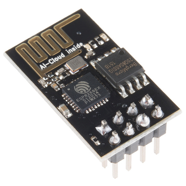 |
| ESP8266 Module |
Wemos Mega is Arduino Mega compatible board plus additional ESP8266 with 32Mb Flash. It allows flexible configurations for connections between ATmega2560, ESP8266 and USB serial. Arduino sketches can be uploaded to ATmega2560 or ESP8266 via USB separately and they can either work together to form a system or independently. The configurations are set by the onboard DIP switches.
The onboard ESP8266 can be flashed with popular firmwares like NodeMCU firmware or ESP8266 AT command-set firmware, as well as be programmed with Arduino IDE.

DIP Switch Configurations

An additional switch configures which serial UART (Serial0 or Serial3) that ESP8266 is connected to. It is possible to connect USB to RX0/TX0 of ATmega2560 and ESP8266 connects to RX3/TX3 of ATmega2560 at the same time, as following:

Let's DIY a simple IoT project!
Hardware:
- Wemos Mega (ATmega2560+ESP8266)
- Mini Bread Board
- Micro USB data cable
- Arduino IDE
- Mobile Phone
- 1 *LED
- 1 *220 ohms Resistor
- Male-male jumper wires
- Smart Phone
Circuit Diagram:
 |
| Wemos mega interfaced with LED |
Code:
ESP8266 Code:
Here two codes are to be loaded into the board.One for creating a local server for communicating using smartphone and other code for making the ESP8266 to access the I/O pins of Atmega-2560 microcontroller.
While uploading this code,DIP switches-5,6,7 should be kept ON ans UART switch is to be kept at RXD0-TXD0. Then upload the code found in this link:
MEGA 2560 Code:
After uploading the above code, DIP Switches 1,2,3,4 should be kept ON and the UART switch is to be kept at RXD3-TXD3. This mode establishes serial communication between Esp8266 and Atmega2560. Then upload the code found in this link:
ESP8266-MEGA Code
MEGA 2560 Code:
After uploading the above code, DIP Switches 1,2,3,4 should be kept ON and the UART switch is to be kept at RXD3-TXD3. This mode establishes serial communication between Esp8266 and Atmega2560. Then upload the code found in this link:ESP8266-MEGA Code
How It Works?
So finally we made a simple IoT project. We've created a local server which an be accessed by using the module's IP address.This is how a basic IoT technology works!
Have a look at this video!
Thank You!
Stay tuned for more updates!!!
Comments
Post a Comment